Take-Off Performance Model

I have spent the last 4-6 weeks working through the complexity of adding a high-fidelity take-off performance forecasting capability to RAWAvCon. It is now at a standard that is good enough to declare it operational. It can be used to forecast absolute Take-Off Field Lengths (TOFL) or take-off flight profiles with reasonable accuracy or to determine the changes in TOFL or flight profiles as a function of user defined changes to the aircraft model, engine model or the take-off regulations.
The TO performance capability has either been used, or will be used in the near future to define baseline take-off performance characteristics for each of the RAWAvCon aircraft models, A320 (including A319 and A321), A330, A350, 737 , 757 , 787 families (all variants of each)
The addition of additional fidelity and capability will be reviewed based on my own and customer requirements. Potential extensions are described below.
Potential uses for this capability
i) Higher fidelity analysis of new/unfamiliar aircraft - no airframe company support needed
a) Airport planning/obstacle analysis
ii) Technology studies that may impact specific aspects of TO Performance
a) Of particular interest for Hybrid/All-Electric and/or distributed propulsion aircraft
b) Modelling TOFL impact of winglets is an early test of the system (data available)
iii) Impact of design changes on TO Noise profiles (identified extension required)
iv) Impact of operational changes on TO departure profiles
v) Departure noise calculation (cert. and ops.) with cutback optimisation (future capability)
v) Plus, any other uses a customer may identify
Model Features
The current take-off performance model assesses TOFL for a user defined altitude and temperature and includes many important internal modelling routines. These include:
i) Engine thrust as a function of Mach number, pressure altitude and ambient air temperature
ii) Low speed free air aerodynamic drag based on aircraft geometry and slat/flap settings
iii) A 'ground effect' model
iv) A gear drag model
v) An engine windmill drag model based on frontal area
vi) An asymmetric control drag term based on differential thrusts, windmill drag and fin aero.
vii) An assumed fully braked deceleration rate (dry runway)
viii) 'Accel-Stop' transition choice (currently Amnd 25-92) - more to be added
ix) A VCMG model using fin CLMax and the asymmetric engine thrust (incl Windmill) and geometry
x) Acceleration factors for constant CAS flight.
The better the data available to tune these various inputs, the more representative the outputs. Clearly, where a customer can provide guidance on an increasing number of these factors, the results will be increasingly representative. However, even where these data are not available, all factors can be tuned to match any published TO performance data given their different effects of the factors on different elements of the TO calculation.
A full TOFL assessment as a function of TOW and flap setting is shown below.

This tuning of the various factors has been performed for a range aircraft types with limited available data to establish some best practise and trends. This knowledge is combined with typical aircraft design and sizing conventions to create reasonable TO performance models for new aircraft types.
Once a TO model is tuned, it should provide an accurate representation of the impact of moderate changes to any of the model features.
Modelling Process:
i) OEI and AEO VMUs defined based on drag, geometry pitch limits and thrust angles
a. OEI = One Engine Inoperative
b. AEO = All Engines Operating
c. VMU = Minimum Unstick Speed - lowest speed an aircraft can be airborne, typically with tail on the ground
ii) Rapid and normal rotation rates used as required for VR and V1 calculation as appropriate
a. VR - Rotation Speed - when the pilot initiates a pitch up command to allow lift off
b. V1 - Take-Off Decision speed. If the aircraft is not braking when it reaches this speed, it must take off
iii) Balanced Field Length calculated (optimum V1) where not VMCG limited
a. VMCG = Minimum Control Speed on the Ground, lowest speed an aircraft can stay <30ft of runway centre line with engine failed
iv) Factored AEO TOFL calculated
iii) V2 based on most critical of various criteria, factored VMU, Flap CLMax and climb gradient, etc
a. V2 - TO safety speed, minimum safe flying speed at between 35-400ft (maybe higher) - required margin to stall speed
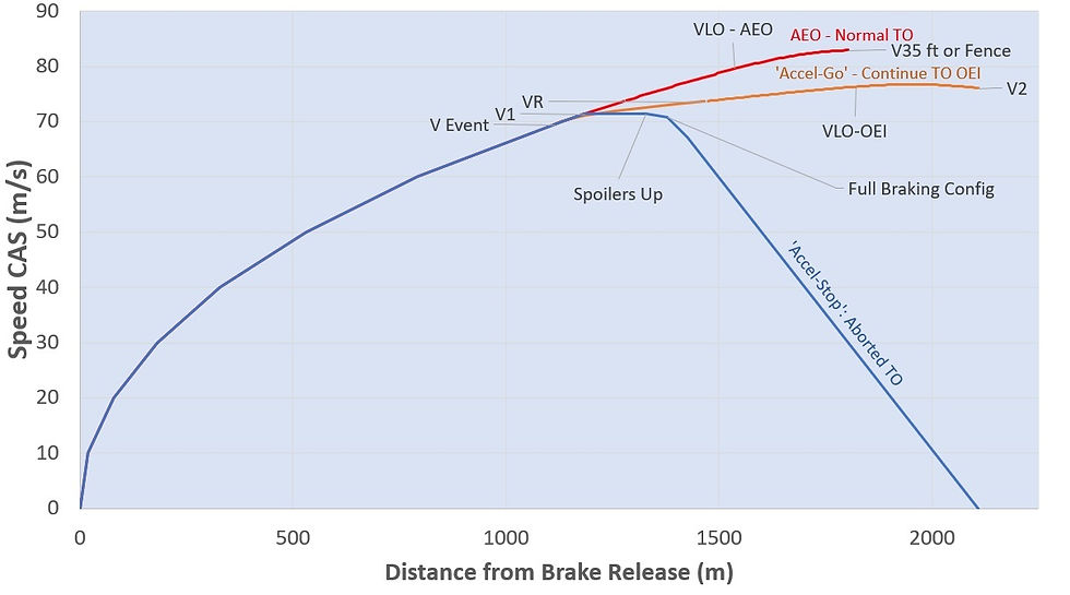
The following image shows aircraft speed plotted against the distance from Brake Release weight for an 'Accel-Stop', an 'Accel-Go' (both with an engine failed) and normal AEO departure.

One point of note, I am continuing to think about is the small speed decay at the end of the 'Accel-Go' plot.
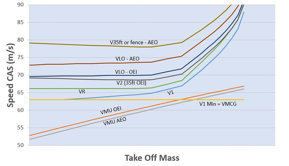
The following chart shows how the various V speeds vary as a function of Take-Off Mass for a single flap setting. This is repeated in the calculation for all flap settings. It is noticeable that he V2 is slower than VLO-OEI at all weights.

Calculation options; TO Performance calculated:
i) as a range of Take-Off Mass (TOM) from design Zero Fuel Mass (ZFM) to just beyond Maximum TOM (MTOM) for each flap with a viable TOFL
a) VMCG and basic minimum V2 limits calculated to the 2nd Segment gradient mass limit
b) 2nd segment gradient mass limit calculated and field length assessed
c) Improved Climb TOFL calculated from 2nd segment mass to maximum possible TOM.
ii) at a single user defined TOM
a) Find TOFL for the greatest flap deflection not using improved climb
b) Calculate feasible improved climb options, (where possible) at all greater flap deflections
Future Development Ideas:
There are some omissions that may be added and simplifications that may be revisited if required by customer or internal demand. These include:
i) Higher fidelity aero braking model with spoiler delta CD and CL as a function of geometry
ii) Higher fidelity braking - wheel brake characteristics with energy and torque limits
iii) Extended flight path to for noise profiles at a selected flap setting
a. Includes a control system to hunt required pitch to maintain desired speeds (e.g. V2+10)
b. Control system to start thrust 'cutback' at a defined height to fly a constant flight gradient
b. Includes a model to model gear door (drag) opening and gear retraction
iv) 4th Segment limits with maximum continuous thrusts
iv) VCMA (min control speed in flight) model - currently assumed to be the same as VCMG
v) Runway Slope (maybe even splitting the runway into multiple sections with different slope)
vi) Wind effects
vii) Derate and ATM thrust reduction modelling
viii) Add turn performance to create a full 3D flight profile, i.e. turn performance.
ix) More detail rotation analysis - model elevator deflection and impact on rotation rate inertia
x) Calculate limiting TOW, derate for a given runway definition, wind and temperature/pressure
xi) A noise model to calculate departure noise characteristics
xii) Automatic Power Reserve (APR)


